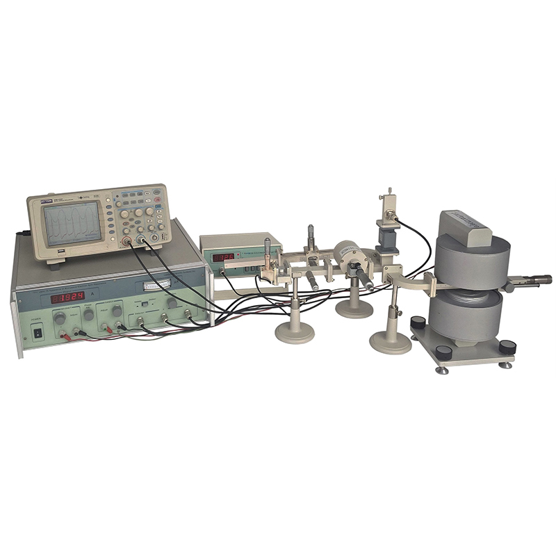
LADP-3 Microwave Electron Spin Resonance Apparatus
Electron spin resonance is also called electron paramagnetic resonance, which refers to the phenomenon of resonance transition between the magnetic energy levels of the electron spin magnetic moment when it is affected by the corresponding frequency electromagnetic wave in the magnetic field. This phenomenon can be observed in paramagnetic materials with unpaired spin magnetic moments (i.e. compounds containing uncoupled electrons). Therefore, electron spin resonance is an important method to detect uncoupled electrons in matter and their interaction with surrounding atoms, so as to obtain the information about the microstructure of the material. This method has high sensitivity and resolution, and can be used to analyze the material in detail without damaging the sample structure and no interference to chemical reaction. At present, it is widely used in the research of physics, chemistry, biology and medicine.
Experiments
1. Study and acknowledge electron spin resonance phenomenon.
2. Measure Lande’s g-factor of DPPH sample.
3. Learn how to use microwave devices in EPR system.
4. Understand standing wave by changing resonant cavity length and determine waveguide wavelength.
5. Measure standing wave field distribution in resonant cavity and determine waveguide wavelength.
Specifications
| Microwave System | |
| Short-circuit piston | adjustment range: 30 mm |
| Sample | DPPH powder in tube (dimensions: Φ2×6 mm) |
| Microwave frequency meter | measurement range: 8.6 GHz ~ 9.6 GHz |
| Waveguide dimensions | inner: 22.86 mm × 10.16 mm (EIA: WR90 or IEC: R100) |
| Electromagnet | |
| Input voltage and accuracy | Max: ≥ 20 V, 1% ± 1 digit |
| Input current range and accuracy | 0 ~ 2.5 A, 1% ± 1 digit |
| Stability | ≤ 1×10⁻³+5 mA |
| Strength of magnetic field | 0 ~ 450 mT |
| Sweep Field | |
| Output voltage | ≥ 6 V |
| Output current range | 0.2 ~ 0.7 A |
| Phase adjustment range | ≥ 180° |
| Scan output | BNC connector, saw-tooth wave output 1~10 V |
| Solid State Microwave Signal Source | |
| Frequency | 8.6 ~ 9.6 GHz |
| Frequency drift | ≤ ± 5×10⁻⁴/15 min |
| Working voltage | ~ 12 VDC |
| Output power | > 20 mW under equal amplitude mode |
| Operation mode & parameters | Equal amplitude |
| Internal square-wave modulation | |
Repetition frequency: 1000 Hz
Accuracy: ± 15%
Skewness: < ± 20%Voltage standing wave ratio< 1.2Waveguide dimensionsinner: 22.86 mm × 10.16 mm (EIA: WR90 or IEC: R100)
Parts List
| Description | Qty |
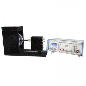
| Main Controller | 1 |
| Electromagnet | 1 |
| Support Base | 3 |
| Microwave System | 1 set (including various microwave components, source, detector, etc) |
| DPPH Sample | 1 |
| Cable | 7 |
| Instructional Manual | 1 |


