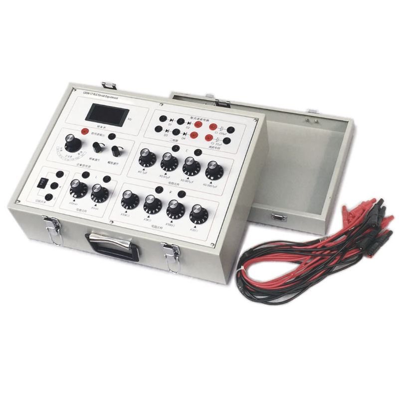
LEEM-17 RLC Circuit Experiment
Experiments
1. Observe the amplitude-frequency characteristics and phase-frequency characteristics of RC, RL, and RLC circuits;
2. Observe the series and parallel resonance phenomena of the RLC circuit;
3. Observe the transient process of RC and RL circuits and measure the time constant τ;
4. Observe the transient process and damping of the RLC series circuit, and measure the critical resistance value.
The main technical parameters
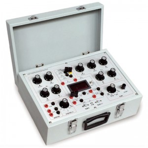
1. Signal source: DC, sine wave, square wave;
Frequency range: sine wave 50Hz~100kHz; square wave 50Hz~1kHz;
Amplitude adjustment range: sine wave, square wave 0~8Vp-p; DC 2~8V;
2. Resistance box: 1Ω~100kΩ, minimum step 1Ω, accuracy 1%;
3. Capacitor box: 0.001~1μF, minimum step 0.001μF, accuracy 2%;
4. Inductance box: 1~110mH, minimum step 1mH, accuracy 2%;
5. Other different parameters can also be customized. A dual trace oscilloscope should be self-prepard.


